
How to Design SMC and DMC Molds: Fiber, Shrinkage and Sump
Table of Contents
A 30 percent glass SMC bracket cut with one radial shrink number comes off the press 0.1 mm long along the flow and 3 mm long across it. On a 400 mm panel that cross-flow miss is 0.8 to 1.5 percent of the print, enough to move every bolt center out of a 0.5 mm hole tolerance. The rework is a new cavity half, and on a 4-cavity automotive bracket tool that is a 12 to 16 week replacement inside a launch schedule with no slack. Sheet molding compound and dough molding compound are not mineral-filled phenolics under different names. They are 20 to 30 percent glass loading that changes shrinkage, abrasion and charge geometry, and the mold has to be designed around all three.
This guide covers compression molds for SMC and DMC, plus the DMC-injection variant, as shop-floor and buyer-side numbers you can put on a drawing.
The Snapshot
- Shrinkage is directional, not radial. A 30 percent glass SMC shrinks 0.05 to 0.25 percent along flow and 0.8 to 1.5 percent across it, so one shrink number cannot size both axes of the cavity.
- The cure window is 135 to 155 °C with 20 to 60 seconds of dwell per mm of wall. A 6 mm bracket holds the platens closed for 2 to 6 minutes per shot.
- Charge to volume, pack through a sump. The charge is 95 to 105 percent of cavity volume plus the flash land, and the sump runs 8 to 15 percent of part height so the material meets on a compression stroke.
- Steel is a wear decision, not a default. Fiber-laden compound cuts a witness groove into P20 within 5,000 to 10,000 shots, so shut-offs get tungsten or hardened 420 banding and the tool is built for 50,000 to 200,000 shots before a re-finish.
SMC vs DMC vs the Phenolic Baseline
Sheet molding compound starts as continuous glass roving 25 to 50 mm long, wetted into a polyester, vinyl ester or epoxy paste and sandwiched between two carrier films. The molder cuts the sheet to pattern, deburrs the film and stacks plies into the cavity. Dough molding compound is the same chemistry with the fiber chopped to 6 to 12 mm and mixed into a stiff dough that ships in logs or pellets with no carrier film.
The landed compression-mold baseline for BMC and phenolics is in the thermoset compression mold guide, and the difference is what the fiber does to the tool. Mineral-filled phenolics shrink close to radial, so one shrink number sizes the cavity. A 20 to 30 percent loading of 25 mm glass does not shrink radially, and it abrades steel the way a mineral filler never will.
Fiber length is the first design lever. The 25 to 50 mm roving in SMC cannot turn easily, so it locks in the direction it was pushed and the part anisotropy follows the flow map. Chopped 6 to 12 mm fiber in DMC rotates more freely, so DMC tolerates a longer, more tortuous flow path and shows a narrower gap between the flow and cross-flow shrink classes.
Both compounds cure in the same thermal window, 135 to 155 °C, and the dwell rule of thumb is 20 to 60 seconds per mm of part thickness. A phenolic BMC mold and an SMC mold can share a platen temperature, but they cannot share a shrink map, a shut-off material or a charge geometry.
Directional Shrinkage and Shrink Classes
Directional shrinkage is the number that decides the cavity drawing. On a 30 percent glass SMC, the flow axis moves 0.05 to 0.25 percent while the cross-flow axis moves 0.8 to 1.5 percent. On a 400 mm panel the mold maker is cutting two axes 15 times apart, and a single CAD scale factor applied to both axes guarantees a dimensional failure in one of them.
Shrink class comes from the compound, not from the part. Low-profile grades, which use a styrene adduct to counter the cure shrinkage, sit between -0.1 and +0.2 percent and can expand. Glass content, fiber length, cure pressure and part thickness all move the class, so the charge lot has to carry a stamped shrink class and the cavity has to be cut against that class. Specify the class on the tooling purchase order, and require the compound lot certificate at every trial.
| Material state | Fiber form | Shrink along flow | Shrink across flow | Cure and dwell |
|---|---|---|---|---|
| SMC, 30 percent glass | Continuous 25 to 50 mm roving | 0.05 to 0.25 percent | 0.8 to 1.5 percent | 135 to 155 °C, 20 to 60 s per mm |
| Low-profile SMC | Continuous 25 to 50 mm roving | -0.1 to +0.2 percent | Class stamped on the charge lot | 135 to 155 °C, 20 to 60 s per mm |
| DMC, compression route | Chopped 6 to 12 mm fiber | Narrower spread than SMC | Narrower spread than SMC | 135 to 155 °C, 20 to 60 s per mm |
| DMC, injection route | Chopped 6 to 12 mm fiber, shear-aligned | 25 to 40 percent above compression | 25 to 40 percent above compression | 135 to 155 °C, 20 to 60 s per mm |
← swipe to scroll →
Table note: shrink, cure and dwell bands are typical industry values for glass-loaded SMC and DMC. Confirm every number against the compound supplier's shrink card for the exact lot before the cavity is cut, and read the resin-vs-resin logic in the thermoset vs thermoplastic guide.
The practical consequence is measurement planning. The first-article layout calls out flow direction and cross direction as separate datum axes with separate tolerances, because one isotropic tolerance band hides the failure mode the compound creates.
Charge Design and the Sump Rule
A compression mold for SMC does not close on an empty cavity. The cavity carries a female register pocket, a raised box around the part outline, and the charge is stacked inside that pocket. When the platens meet, the register lands crush the excess into a controlled flash land instead of letting it run to the edges of the tool. That pocket geometry, called a sump or a feed pocket, is what turns hydraulic crush into a compression stroke.
Sump depth is the number to get right. Set it at 8 to 15 percent of the finished part height, so the two faces of compound meet on a compression stroke with pressure left to pack the part. A sump deeper than 15 percent wastes cure time heating a thick feed mass, and a shallower one lets the register land bottom out before the cavity fills, which prints a short shot or a sink you cannot pack out.
Charge weight comes from volume, not from a scale guess in the shop. Compute the cavity volume, add 2 to 5 percent for the flash land, and cut the charge to 95 to 105 percent of that total. SMC is supplied with a measured cured density, typically 1.6 to 1.9 g per cubic centimeter on glass-loaded grades, so the pattern cutter, the ply count and the stack height follow from that density figure.
SMC plies are oriented on purpose. A bracket that needs stiffness in one axis gets its 25 mm fiber laid 45 to 90 degrees to that axis in the outer plies, with cross plies inside. Cut ratios of 1.3 to 1.7 stretch the sheet and raise fiber alignment, so the drawing states the ply map the same way it states the shrink class.
DMC in a compression mold is simpler to place and harder to meter. The dough comes in logs, so the shop weighs charges to plus or minus 2 percent and drops them loose into the register. For DMC injected-molded at a press of 70 to 100 bar, the rule flips to a 3 to 8 percent overcharge, because the intensification pin has to pack the extra volume into the closed cavity rather than bleed it to flash.
Fiber Orientation and the Sink Map
Fibers rotate with the flow front, so an SMC or DMC part is never homogeneous. The skin next to the steel runs fiber-rich, the core runs resin-rich, and the difference between the two layers is what a sink mark, a burnish line and a paint-bake crack all feed on. The mold designer cannot remove that structure, only decide where it shows.
Gate and charge placement set the weld line. Where two flow fronts meet, the fibers on each side lie parallel to the front they rode, and the meeting plane is weak and shrinks on a step. A 0.4 to 0.8 mm weld on a 3 mm wall can open into a visible crack through a 140 to 160 °C paint bake, so the drawing should put weld lines in zones the part never sees in service.
Keep gates at the thickest section. SMC and DMC lose pack pressure fast once the skin gels, and a gate landing on a thin wall sinks while the thick section beside it feeds nothing. If the part has a rib or boss cluster, place the charge or the gate over the heaviest mass and let the flow run toward the thin areas, not the other way around.
Draft is a hard requirement because the cured part cannot be flexed off a core. Allow 0.8 to 1.2 mm of draft per 25 mm of draw depth, which on a typical 2-degree included angle lands near 0.9 mm per 25 mm. A 40 mm deep wall needs a side action or a tapered core, not a steeper pull.
Sharp internal corners are out of bounds for SMC. The 25 mm fiber cannot turn a knife corner, so the compound bridges a 1 mm inside radius and leaves a void pocket under the surface. Specify R2 as a working minimum on inside corners, and put a rib fillet of at least half the rib height wherever a rib meets a wall.
Flash Land and Shut-Off Numbers
The flash land is the parallel strip the register closes on, and its size decides whether the part holds dimensions or bleeds pressure. On SMC press molds, run the land 0.2 to 0.5 mm thick and 3 to 6 mm wide. Too thin a land lets the steel hit before the cavity packs; too thick one leaves a feathered flash edge that a finishing robot cannot grip cleanly.
DMC wants a deeper land, 0.5 to 0.8 mm, because the dough carries more volatile and needs to bleed air before the steel closes. The land width stays at 3 to 6 mm, and the volume of that annulus is the 2 to 5 percent already built into the charge calculation. The wider land also holds the DMC's higher bleed rate without locking the mold over-trapped.

Shut-off edges are the wear hot spot, and they justify their cost by the groove they prevent. Edge-band the lands with tungsten inserts or hardened 420 stainless at 48 to 52 HRC, because fiber-laden compound cuts a witness groove into P20 within 5,000 to 10,000 shots once the land starts kissing. A banded edge takes 2 to 3 re-dressings across the tool life; a banded P20 land takes one rebuild.
Vents move next. Styrene and water vapor come off the polyester paste during cure, so cut vent grooves 0.05 to 0.10 mm deep into the parting line on the fixed side, and put blind vents at the last-to-fill corner where the gas gets trapped. A vent shallower than 0.05 mm plugs with cured resin in a few hundred shots, and one deeper than 0.10 mm prints a fin on the parting line.
On a first-article run, breath the press by opening it 1 to 3 times mid-compression so the volatile leaves before the skin seals it in. Breathing is a process move, not a mold fix, but a mold that has to breathe on production shots is a mold with under-depth vents. The same trapped-gas logic in thermoplastic form drives fin and blister on any parting line that cannot bleed.
Mold Steel and Surface Treatment
The cavity block starts at 1.2344 or H13 prehardened to 48 to 52 HRC, which survives an SMC tool at 50,000 to 200,000 shots without a hardness loss that matters. For parts that see a corrosion inhibitor in the compound, or tools that sit through humid shutdowns, 420 stainless at the same prehard range buys the corrosion margin, and it bands the shut-offs cleanly.
The working face gets a coating for two reasons: anti-stick and polish drag. A 25 to 40 µm hard chrome layer keeps glass fiber from welding micro-scratches into the steel and lets the A-side polish survive re-cleanings. Electroless nickel at 45 to 55 µm is the alternative where the geometry has deep corners that hard chrome shields out of its thickness.

Do not chase a mirror everywhere. SMC copies the steel at about 0.05 mm fidelity, so a scratch, a pit or a polish swirl on the A-face prints onto the bracket and stays there. Put the optical finish only on the cosmetic face and hold the rest of the cavity at a documented SPI grade, because an all-mirror tool doubles polish hours and buys nothing on the B-side.
Abrasion is the number that ends the P20 debate. The glass in SMC is a cutting edge carried through a flow, and it plows grooves along the flow direction on any face softer than about 50 HRC. That is the same wear arithmetic the glass-filled resin tooling guide works for thermoplastics, with the fiber long enough in SMC to make the grooving directional.
Press Interface and Platen Temperature
The mold is designed against the press you run it on, and that interface starts with the mounting pattern. Hydraulic compression presses carry a bolt grid on 100 to 200 mm centers, so the mold base is drawn to that grid before the cavity is laid out. A tool drilled for a 200 mm pattern cannot be shimmed onto a 100 mm platen without a transition plate that adds height the daylight did not budget.
Set the mold height inside 60 to 70 percent of the press daylight so the ram keeps travel for the charge and the part. On a 4-post hydraulic running compression SMC, size the clamp against a cavity pressure of 4 to 10 MPa on projected area. A 600 by 400 mm projected panel needs 960 to 2,400 kN, and that number sets the frame the tool has to fit, not the other way around.

Heated platens run 140 to 150 °C on polyester SMC, with 3 to 6 kW of element power per platen and a thermocouple in each corner. Uniformity beats absolute setpoint, because cure kinetics freeze fiber orientation at the gel point. Hold plus or minus 5 °C across the working face and the shrink class behaves the way the supplier card says. A corner 10 °C cold shrinks that end differently and the panel comes out bowed.
The mold has to hold that uniformity. A heavy B-side block, with 20 to 30 mm of steel between cavity and element plate, damps the swing, and the heater layout should concentrate power at the corners the platen loses first.
DMC Injection Tooling Specifics
DMC injection tooling moves the same dough through a runner instead of dropping it into a sump, and every number shifts. The compound stays extrudable at 10 to 20 mm in a round runner, so the feed system is built at that scale, not at the 1 to 3 mm gates a thermoplastic tool would use. The runner itself is cooled or insulated to 60 to 100 °C so the dough does not skin inside the feed path.
The nozzle lands open. Run a 0.5 to 1.0 mm open land at the tip and skip any gate seal, because DMC cures onto a hot tip and a sealed nozzle becomes a plug that has to be drilled out at every stoppage. Intensification happens behind a check ring or a free piston, and the shot closes with the same 3 to 8 percent overcharge packed into the cavity.
Expect 25 to 40 percent more shrink on the injection route than on compression for the same compound, because runner shear aligns the chopped 6 to 12 mm fiber along flow. A cavity sized to the compression shrink card runs short on both axes. Cut the injection shrink into the steel first time.
The transfer-tooling cousin feeds a pot and channels instead of an intensification ram. DMC injection runs 70 to 100 bar of hydraulic pack behind the piston; transfer fills slower at lower pressure, and the vent and land numbers change with the front speed.
Defects Traced to the Tool
Four defects carry most of the scrap on an SMC or DMC line, and each one points at a number on the mold drawing before it points at the charge. The first pass at diagnosis is measuring the tool, not adjusting the press.
| Defect | Tool cause | Number to check | First fix |
|---|---|---|---|
| Surface blister | Styrene trapped under a shut-off that closes before the gas leaves | Vent depth 0.05 to 0.10 mm | Breathe the press 1 to 3 opens, then deepen vents |
| Fiber bloom | Over-shear at the gate or register lip standing fibers on the surface | Widen the gate or charge entry 1.0 to 1.5 mm | Open the entry, do not just raise pack pressure |
| Sink over a rib | Rib too thick to feed from the surrounding wall during dwell | Rib at 50 percent of wall maximum | Core a sump relief behind the rib |
| Part distortion | Uneven platen temperature across the working face | Look for an 8 to 12 °C delta, limit plus or minus 5 °C | Check the corner thermocouples before blaming the charge |
← swipe to scroll →
Table note: causes and fix bands are typical values for polyester SMC and DMC on hydraulic compression presses. Confirm vent depths and land widths on the actual tool before any re-cut, and log the measurements on the first article inspection report.
One ordering discipline saves weeks. Every defect above says measure the steel before touching the compound. A shrink complaint that is really a cold platen corner gets re-tooled against the wrong number. Read platen delta at four corners, then vent depth with a feeler, then the shrink map.
SMC and DMC Mold Design Checklist
Run this list against the drawing before the mold is released to the shop floor. Each line is a number a reviewer can read off the print, not off a trial press.
- Shrink class on paper. Flow axis and cross axis stated separately, matched to the compound lot card, with the low-profile grades carrying the -0.1 to +0.2 percent class explicitly.
- Sump at 8 to 15 percent of part height. Female register pocket drawn, charge at 95 to 105 percent of cavity volume plus 2 to 5 percent flash land, and 3 to 8 percent overcharge noted for DMC injection.
- Flash land 0.2 to 0.5 mm for SMC, 0.5 to 0.8 mm for DMC. Width 3 to 6 mm, volume counted in the charge math.
- Shut-offs banded. Tungsten or 420 at 48 to 52 HRC on every land, because P20 grooves within 5,000 to 10,000 shots under fiber.
- Vent map. 0.05 to 0.10 mm grooves at the parting line, blind vents at last-to-fill corners, clean-out interval written into the maintenance sheet.
- Steel and surface. 1.2344 or H13 prehard 48 to 52 HRC, 25 to 40 µm hard chrome or 45 to 55 µm electroless nickel on the working faces, optical polish on the cosmetic side only.
- Part geometry rules. 0.8 to 1.2 mm draft per 25 mm depth, R2 minimum inside corners, ribs capped at 50 percent of wall.
- Press interface. Bolt grid to the 100 to 200 mm platen pattern, mold height at 60 to 70 percent of daylight, 4 to 10 MPa projected-area pressure, plus or minus 5 °C platen promise.
The checklist doubles as the acceptance file. A tool that ships with its shrink class, charge sheet, land measurements and vent map travels from the mold design and DFM review through a trial and a shutdown with the same numbers on paper that made the first good shot.
The Bottom Line
SMC and DMC tooling is a short list of decisions made against fiber, not against resin. Size the cavity from two shrink numbers, 0.05 to 0.25 percent along flow and 0.8 to 1.5 percent across it on a 30 percent glass grade, with the class stamped on every charge lot. Feed the part through a sump at 8 to 15 percent of part height, close on a 0.2 to 0.5 mm flash land banded in tungsten or 420, and vent styrene at 0.05 to 0.10 mm. Cure at 135 to 155 °C with 20 to 60 seconds per mm, and hold the platen within plus or minus 5 °C so the shrink class stays true.
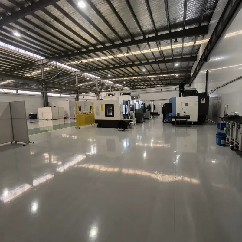
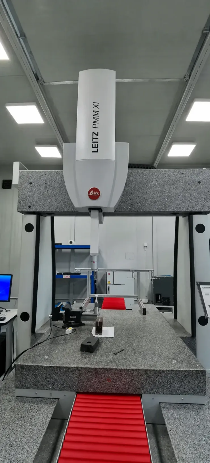
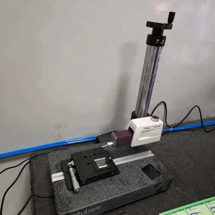
The economics follow the steel. A banded shut-off takes 2 to 3 re-dressings and an SMC tool runs 50,000 to 200,000 shots before a re-finish, while a P20 land grooves in 5,000 to 10,000. DieStrike makes the die under an IATF 16949 quality system, with plus or minus 0.005 mm mold accuracy, plus or minus 0.002 mm on EDM and jig grinding, HRC 62 maximum heat treatment and 120-plus machines behind the build. Tool lead times run 2 to 5 weeks on standard work, and a 4-cavity automotive bracket program lands at 12 to 16 weeks, delivered to the molder whose press it mounts on.
KEEP READING
Related Reading
How to Design Compression Molds for Thermosets
BMC and phenolic compression tooling: the baseline that SMC and DMC depart from on shrinkage and charge geometry.
Read articleArticleThermoset vs Thermoplastic: What the Tool Must Do Differently
Cure chemistry, dwell and heat input decisions that separate a thermoset mold from an injection tool.
Read articleArticleHow to Design Molds for Glass-Filled Resins
Abrasive glass loading and what it does to shut-offs, vents and cavity surface treatment.
Read articleServiceMold Design and DFM
IATF 16949 design reviews for compression and transfer tooling, with 2 to 5 week lead times on standard work.
Read articleNEXT STEP
Ready to Start Your Mold?
Send us your element dimensions or part numbers — our team responds within 24 hours. Pricing and lead time come with the answer.

Written by
Ray ChanExport Brand Manager at DieStrike. Ray helps global importers, distributors and OEMs source factory-direct molds and mold parts.