
How to Design EPS Foam Molds: Steam Jets, Vacuum and Block Tooling
Table of Contents
A shipping corner that crumbles bead by bead does not have a bad batch of foam. It has a cold steam zone, and the weld between beads never formed. EPS molding fuses pre-expanded beads with 1.0 to 3.0 bar of saturated steam inside an aluminum autoclave mold, and every gram of that steam enters through bores 0.8 to 1.5 mm wide. Those jets clog with bead fines and pentane wax somewhere between 500 and 5,000 cycles, and a tool that cannot be cleaned dies on the machine it was built to outlive.
This is buyer-side guidance for the EPS bead-molding tool you commission and hand to the molder you buy from: mold architecture, steam routing, condensate drainage, vacuum drying and the maintenance numbers.
The Snapshot
- Beads expand 200 to 800 times with pentane. Part density is set by the loading: 15 to 30 g/L for protective packaging, 20 to 50 g/L for shapes and blocks.
- Steam admission runs 1.0 to 3.0 bar. Size the total jet area so cavity pressure stays under 20 kPa above supply, or the loose bead bed displaces.
- Jets are 0.8 to 1.5 mm on 25 to 50 mm pitch. Each steam zone needs its own condensate drain, and a 40 to 80 kPa vacuum pull through the bead face dries the part in 30 to 120 seconds.
- Tools cost 3,000 to 30,000 USD and run 50,000 to 300,000 cycles. An injection-molded replacement needs 5 to 30 times the tool cost; bead resin at 1.0 to 1.6 USD per kg dominates the repeat cost.
How Bead Molding Actually Works
Expandable polystyrene beads arrive already foamed. Each bead is a polystyrene shell inflated 200 to 800 times its original volume by pentane blowing agent trapped inside. Density is set by how much bead volume fills the cavity: 15 to 30 g/L for protective packaging, 20 to 50 g/L for shapes and blocks.
Steam does two jobs at once. Admission heat re-activates the pentane, each bead expands further and presses against its neighbors, and the softening surfaces fuse where beads touch. Weld strength at proper fusion lands at 100 to 250 kPa in bead-to-bead tension. A part with failed fusion pulls apart along those weld interfaces, which is why a bad corner sheds intact beads instead of tearing.
The steam has to pass through the bead bed, not just into the cavity. Every weld point you never see sits downstream of a jet, and that sentence is the whole design brief for this tool family. Cycle time runs 3 to 20 minutes by section thickness: a 10 mm skin welds in seconds, a 300 mm block needs repeated steam passes and a long vacuum hold.
EPS Mold Architecture
An EPS shape mold is a two-shell aluminum autoclave. Cast A356 shells carry curved or organically shaped parts; welded 6061 plate carries boxes, liners and panels. Neither shell is pressure-rated beyond the steam circuit it lives in, and the clamping on the machine only has to hold the shells shut against 1.0 to 3.0 bar acting inside the cavity.
The parting line carries a compressible rubber seal around the full perimeter. Steam escaping through the bead bed presses fines into that seal land, and a failed seal line blows a flash fin of loose beads across the parting. Steel or hardened-aluminum wear plates at the fill and steam entry areas take the handling abuse that bare 6061 will not.
The cavity surface is the bead face. Detail resolution tops out at 0.5 to 1 mm, the scale of a single bead, so engraved text reads crisp only when letters stay at 2 mm or larger. Draft needs 1 to 2 degrees minimum on shape-mold walls, more over hand inserts, because the part is released cold and stiff. Shrink allowance runs 0.2 to 0.5 percent, and the honest way to fix your number is a dimensional trial at production density, not a spreadsheet, because shrink moves with g/L and steam pressure. The cavity-sizing rules in the shrinkage compensation guide carry the same logic for molded parts.
DieStrike makes the metal, not the molded foam. We machine and sell jet inserts, wear plates and side-core components for the EPS tool builders and molders we work with as partners, and the same discipline applies: IATF 16949 process control, plus or minus 0.005 mm on milled components and plus or minus 0.002 mm on EDM and jig-ground fits for the core and insert geometry.
Steam Jet Sizing Arithmetic
Steam enters the cavity through drilled jets, and the jet field is the single most important number set on an EPS tool. Each jet is 0.8 to 1.5 mm, drilled on a 25 to 50 mm pitch and facing the cavity. A box liner wall might carry 200 to 400 jets per shell half, which is 150 to 200 meters of 1 mm drilling per tool. It is the labor line that separates an EPS tool quote from a lookalike aluminum casting.
The sizing rule is pressure-based, not flow-based. Total jet area must admit steam fast enough to fill the cavity without letting cavity pressure climb more than about 20 kPa above the supply side of the bed. Above that differential, the loose bead bed behaves like a fluid: beads lift, migrate and re-settle, and the part comes out with a density gradient or a void pocket near the top. Under the 20 kPa ceiling, the beads stay where you loaded them.
Sizing works as a flow-per-area budget. A wall zone with 40 jets at 1.0 mm carries roughly 31 mm2 of throat area. Halve the jet count on the same zone and the steam time to reach weld temperature stretches well past the setpoint, so the operator compensates with longer admission, more condensate and a wetter part.
Jet geometry matters as much as count. Drill the through-hole perpendicular to the cavity face and counterbore from the back; an angled 0.8 mm jet wanders in deep aluminum and lands as a blind spot that no inspection from the front will explain. Group jets so each one feeds a patch of face roughly 25 to 50 mm in radius, then check the pattern against the part geometry, not against a generic grid drawing.
Jet Placement Rules and Blind Spots
Place jets per wall, and think in weld time per section. A 15 mm-thick wall needs roughly 30 to 40 seconds of weld steam with effective admission on both faces of the wall, because heat has to reach the bead-to-bead contact plane at the middle of the section. Steam arrives from both shell halves, condenses at the bead surface, and the fusion front walks inward from each face. One-sided steam leaves a cold center line that splits like a dry seam.
Blind spots are placement failures, not machine failures. A boss, a deep rib root or the shadow of a hand core can sit outside every jet radius. The signature on the part is unmistakable: beads you can pull out with your fingers, whole and unfused, from a defined pocket. Before blaming the machine, map the pocket against the jet drawing and count the jets within 50 mm of it.
Deep features need local steam concentration, not global pressure. Add jet density inside the cavity of a deep box corner and put a drain directly under it. Raising the whole zone pressure from 1.5 to 3.0 bar to chase one cold corner overfills the rest of the part, drives more condensate everywhere and pushes cavity pressure toward the 20 kPa displacement ceiling on the open wall faces.
The same place-vents-at-the-last-to-fill instinct from conventional tooling applies here; the general physics are laid out in the mold venting guide. In an EPS mold the air escapes through the bead bed itself and out the drains, so the jet map and the drain map are one drawing. A jet field with no drain below it steams a puddle.
Condensate Drainage
Every steam zone needs its own condensate drain, and this is the line buyers cut and the repair bill that follows. Steam that condenses on the cold bead face turns to water inside the cavity, and the only exit is the drain network sized for it. A zone without a drain reads on the part as wet cold spots: darker, heavier patches where fused beads sit in a matrix of partially fused fines, sometimes 5 to 20 g above nominal part weight.
Drains are open passages, not jets. Where a jet is 0.8 to 1.5 mm, a drain path is commonly a group of 2 to 4 mm holes or a machined channel routed to the shell edge and out through a quick coupling. Water has to leave against the same 20 kPa pressure budget that keeps the beads in place, so undersized drains and oversized inlets fight the same differential.
Drain routing is gravity, and the mold orientation on the machine fixes the plan. Put drains at the bottom of every cavity low point, including the bottoms of deep bosses, and slope internal passages toward them. A drain that terminates above the local low spot becomes a condensation trap that never fully blows down between cycles.
Valves deserve as much design attention as jets. Steam and vacuum valves on an EPS machine cycle thousands of times per month, and a lazy valve shows up as a soft-start defect on the part. Diaphragm valves beat ball valves for steam and vacuum service here: the diaphragm seals against fines, repeats its stroke count after count and fails in an open or closed position you can diagnose, while a ball valve wear path starts to bleed steam into an exhausted zone.
Vacuum Drying and Cycle Time
Vacuum is the second half of the steam system. After weld, a vacuum pull at 40 to 80 kPa differential draws air and pentane-steam mixture through the bead face and out the drains, drying the part from the inside. Dwell time runs 30 to 120 seconds by section thickness. Skip it on a thick block and the part leaves the mold wet, soft and dimensionally unstable, gaining 1 to 2 percent in weight variation across the run.
Vacuum lines pull through the same bead face the steam did, so the drain network doubles as the drying network. This is why one drawing covers jets, drains and vacuum ports: a zone with good steam admission and poor vacuum evacuation still exits the machine with a wet core. On 10 to 30 mm packaging walls, the vacuum step cuts total cool-down from around 5 minutes of passive waiting to under 2 minutes of active drying.
Cooling before opening is non-negotiable. The pentane in the beads wants to keep expanding as the part cools, and the vacuum hold counterbalances that until the polystyrene is below its softening point, roughly 85 to 100 °C for the bead grade. Open early and the part blisters, grows a percent of linear dimension and picks up a rough frosted skin from cell rupture at the surface.
Jet Clogging and Clean-Out
Jets clog. Bead fines and pentane wax work through the bead bed and plug 0.8 mm bores somewhere after 500 to 5,000 cycles, depending on bead grade, steam quality and how often the tool is back-blown. A clogged zone announces itself exactly like a placement blind spot: a defined pocket of pull-out beads. The difference is that a design blind spot is stable cycle to cycle, and a clog grows.
Design the clean-out before you commit the drilling plan. Every jet needs wire access from the back: the through-hole must stay straight and unobstructed inside the shell, with nothing machined across it later. A 0.6 mm clean-out wire pushed from the back clears a waxed 1.0 mm jet in seconds during a 30-minute lunch break; the same jet in a tool with a counterbore cross-drilled by a coolant passage needs shell disassembly and a day.
Removable jet inserts save tools. Instead of drilling the shell directly, press-fit hardened, ground jet plates or screwed jet studs over the high-clog zones, the fill corner and the steam inlet. When a zone clogs beyond wire cleaning, swap the insert rather than re-cutting the shell. A replaceable jet insert is the same job as a conformal or baffle insert on an injection tool: the wear item is where you can reach it.
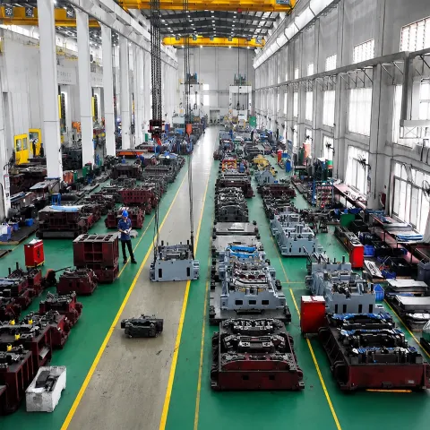
Track clog rate by zone and it becomes a maintenance schedule, not an emergency. If a corner plugs every 1,500 cycles, add it to the weekly wire pass, re-cut the local jet density at the next rebuild or move to a 1.5 mm jet with more, smaller inlets to keep the same throat area. Log jet pressure-drop readings at every PM, and the tool tells you which zone is dying before the part does.
Side Cores and Hand-Loaded Inserts
EPS molding has no hydraulic slide bank, no lifters and no collapsing cores in the injection-mold sense. Undercuts are solved with hand-loaded metal inserts placed in the open mold before closing, or with geometry that avoids the undercut entirely. A side pocket in a cooler liner means a hand core, a handle means a wire core pressed into the cavity before steam, and a through-hole means an insert pin.
Hand cores live or die on surface temperature. A cold aluminum core sits against beads at 1.0 to 3.0 bar steam and becomes a heat sink: the fusion front stalls at the core face and the beads weld to the steel instead of to each other. The fix is a core that arrives warm, 60 to 90 °C from a hot plate or a steam bath, vented at the tip so trapped air does not print a dimple, and polished to Ra 0.4 or better so the fused skin releases.
Wire cores for handles are simple and unforgiving. A 2 to 4 mm steel wire pressed 20 to 30 mm into the bead bed fuses into the part and stays there; pull it out and you leave a smooth tunnel. Insert pins that are removed after molding leave witness holes, and every hole is a quote line: does the customer see it, does it need a plug, what tolerance does the tunnel hold after fusion shrink moves it 0.2 to 0.5 percent.
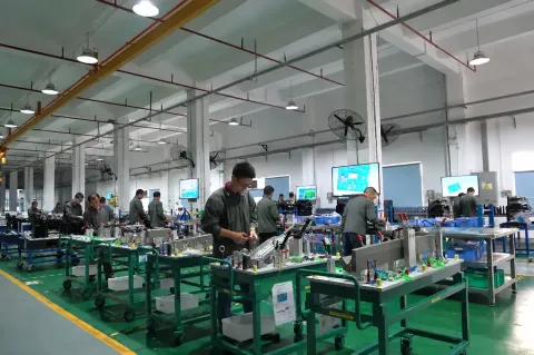
Each hand insert is a cycle-time tax you should count before tooling. Loading, seating and unmolding one core by hand can add 20 to 60 seconds per cycle, and a part with three inserts carries that tax on every single part for the life of the program. That number belongs in the piece-price model next to the tool price, because the molder will charge it either way.
Mold Life and Maintenance
Aluminum EPS molds run 50,000 to 300,000 cycles depending on shell thickness, handling discipline and how fast the jet zones clog. The failure modes are slow and visible: parting-face erosion from steam and bead fines, seal-groove widening, jet clogging, wear-plate scoring and handle abuse on the shell edges. None of them are catastrophic, which is exactly why shops defer all of them until the part starts reporting the tool's condition.
Parting-face erosion re-welds. Aluminum shells that lip or wash out at the seal land get built up with aluminum filler wire and re-machined, a 2 to 6 hour shop job per face that restores the seal geometry. Replace the elastomer seals every 5,000 to 20,000 cycles, or on any zone that blows fines through the parting. Log part weight weekly: a part drifting 1 to 2 percent heavy is reading a swollen seal or a blocked drain, before either shows visually.
| Item | Interval | Failure if skipped |
|---|---|---|
| Jet clean-out (wire pass) | Every 500 to 5,000 cycles by zone | Pull-out bead pockets that grow cycle over cycle |
| Parting seal replacement | 5,000 to 20,000 cycles | Fines blown through the parting, flash fins |
| Parting-face survey and re-weld | At erosion, typically 20,000-plus cycles | Leak path starves the adjacent jet zone |
| Drain blow-down check | Daily | Wet cold spots, 5 to 20 g weight gain |
| Steam and vacuum valve service | Per machine OEM schedule, thousands of cycles | Bleed steam into the exhausted zone, soft starts |
← swipe to scroll →
Table note: intervals are typical for packaging and shape molding at 15 to 50 g/L densities. Confirm against your bead grade, steam quality and the machine OEM manual before setting the PM plan.
Track the tool like an asset, the same way a steel program is tracked. Cycles logged, zones cleaned, seals dated, shrink re-verified after every weld repair. A mold-asset register keeps an EPS tool honest at 100,000 cycles, and it carries the same columns a stamped tool register would.
Block Molds Versus Shape Molds
Two families share the bead process and almost nothing else. A block mold is a big rectangular box, often 1 to 3 m in length, that fuses loose beads into a 20 to 50 g/L billet. It has no core side, no cosmetic face, no hand inserts: just jet-lined walls, drains along the bottom and a door that opens after the vacuum hold. Blocks are cut to pattern downstream on hot-wire equipment.
Shape molds are the autoclave tools this guide has described: two shells, defined cavity geometry, parting seals, hand cores, cosmetic or functional faces. The block tool is cheaper and cruder because a billet face is sawn away; the shape tool carries every jet rule because its face is the part. When you buy foam, decide first which family your part lives in, because the tool quotes differ by an order of magnitude in engineering content.
Keep the two neighbors in molding straight. Microcellular foam is a different world: supercritical nitrogen injected into a melt and nucleated inside a conventional closed injection mold, with high-precision steel faces and gas-transfer vents. It is not bead sintering and it does not share this tool logic. The distinction is laid out in the microcellular foam mold guide.
Buyer Economics
An EPS shape tool for a packaging liner or a corner set lands at 3,000 to 30,000 USD depending on part size, jet count and how many hand inserts the geometry demands. The comparison that decides material selection: an injection-molded rigid equivalent needs a precision steel mold at 5 to 30 times that tool budget, plus a press, plus a resin change. EPS wins by owning the low tool line and giving up the repeat line.
On the repeat side, bead resin at 1.0 to 1.6 USD per kg swamps everything else, and density is the price knob. Moving a liner from 25 to 18 g/L cuts bead mass roughly 28 percent and re-opens the fusion question at every wall, because the same part now carries fewer, larger cells with less polystyrene per weld point. Quote the low density honestly: it needs a jet-density re-check, not just a lighter loading hopper.
Talk to the tool builder and the molder with the same three drawings in hand: the part print with density called out per zone, a jet-and-drain map they can price, and the insert list with its per-cycle seconds tax. Where the geometry pushes into tight core fits or repeated insert campaigns, a DFM review catches the weld risk while the file is still cheap, and DieStrike reviews the steel and aluminum component side for the tolerances that actually matter.
The Bottom Line
EPS mold design is steam plumbing executed in aluminum. Beads expanded 200 to 800 times fill a two-shell autoclave tool at 15 to 50 g/L, and 1.0 to 3.0 bar saturated steam fuses them to 100 to 250 kPa weld strength in a 3 to 20 minute cycle. The cavity surface is the bead face: detail stops at 0.5 to 1 mm, draft starts at 1 to 2 degrees, and the 0.2 to 0.5 percent shrink allowance gets fixed by a density-matched trial.
Three systems decide the part. Jet fields of 0.8 to 1.5 mm holes on 25 to 50 mm pitch sized so cavity pressure stays under 20 kPa above supply, with two-sided steam for every 15 mm wall that needs its 30 to 40 second weld. Drains under every zone or the part carries wet cold spots and 5 to 20 g of extra water weight. A 40 to 80 kPa vacuum pull held 30 to 120 seconds that dries the core and cuts cooling from 5 minutes to under 2.
Then plan for clogging, because it is the process, not the accident: 500 to 5,000 cycles before fines and wax close a 0.8 mm jet, straight wire access from the back, removable inserts over the bad zones. Aluminum shells earn 50,000 to 300,000 cycles with re-welded parting faces and seals replaced every 5,000 to 20,000 cycles. DieStrike sells the precision components, jet inserts and hand-core steel behind these tools rather than molding the foam itself, machined under IATF 16949 on 120+ machines to plus or minus 0.005 mm, plus or minus 0.002 mm on EDM and jig grinding, HRC 62 maximum, standard components in 3 to 7 days, tool lead times of 2 to 5 weeks, with tier-1 references including TE, Amphenol, Luxshare and Dongshan.
KEEP READING
Related Reading
Mold Venting: Depth, Location and Design Rules
Blocked outlets write themselves into the part in injection molds and in EPS autoclave tools alike.
Read articleArticle5 Shrinkage Compensation Rules for Injection Molding
Shrink callouts on a density map: the same discipline the 0.2 to 0.5 percent EPS allowance needs.
Read articleArticleHow to Design Molds for Microcellular Foam Molding
Supercritical-nitrogen injection foaming is a different tool entirely. Here is where the paths split.
Read articleServiceMold Design and DFM
IATF 16949 design reviews for jet fields, wear plates and hand-core geometry, with 2 to 5 week leads.
Read articleNEXT STEP
Ready to Start Your Mold?
Send us your element dimensions or part numbers — our team responds within 24 hours. Pricing and lead time come with the answer.

Written by
Ray ChanExport Brand Manager at DieStrike. Ray helps global importers, distributors and OEMs source factory-direct molds and mold parts.