
How to Design Composite Molds: Autoclave Tooling for Prepreg
Table of Contents
A 2 m wing rib cured on a 4140 steel tool ends up 0.9 degrees off the CAD angle when the laminate spring-in was built for a 20 ppm per K epoxy tool. The shop finds it after 40 parts. Every autoclave cycle costs the composite cell 3 to 8 hours of furnace time at 5 to 7 bar, so a drifting tool burns more than scrap: it burns the schedule of the cure. The tool is the only reusable object in a prepreg layup, and the numbers below show what makes it hold the part and survive the cycle.
This guide covers the buyer-side decision path for autoclave tooling: vacuum architecture, CTE match, material ladder, surface, thermal uniformity, matching and trim fixtures, and rework economics. The autoclave belongs to the composite shop; DieStrike machines the metal tool bodies, inserts and fixtures that go inside it.
The Snapshot
- The cycle loads the tool four ways at once. A vacuum bag pulled to 0.8 to 0.95 bar differential under 5 to 7 bar autoclave over-pressure, then 120 to 190 C for 1 to 6 hours at 1.5 to 5 C per minute, every part.
- CTE mismatch prints into angle. Tool steel at 11 to 12 ppm per K against a laminate at 0 to 12 ppm per K drives 0.25 to 1.5 degrees of spring-in and slope error on curved parts.
- Tool cost spans a 40x band. Epoxy laminate tooling runs 8,000 to 40,000 USD for 100 to 500 cycles at a 160 to 180 C ceiling; invar 42 Class A tools run 50,000 to 300,000 USD.
- Vacuum is the acceptance gate. A leak target of 0.1 to 0.5 mbar-L/s across knife grooves 3 to 6 mm deep and ports 3 to 8 mm on 100 to 300 mm pitch is what lets a tool ship at all.
What the Tool Survives Every Cycle
In a prepreg layup the tool sets the A-surface, carries the bag seal, conducts heat to the plies and reacts to autoclave pressure. The cured carbon-epoxy part then shrinks onto it during cool-down. Design it as a pressure vessel interface, not as a mold cavity.
The load sequence repeats every cycle. The bag side sees 0.8 to 0.95 bar of differential from the first evacuation, and the autoclave adds 5 to 7 bar of nitrogen over-pressure outside it. On a 1,000 by 600 mm planar tool, 6 bar pushes roughly 60 tonnes through the bag interface into the tool surface and its backing structure.
Thermal cycling is the fatigue driver. The cure runs 120 to 190 C held for 1 to 6 hours, at 1.5 to 5 C per minute up and down. A steel tool working a 25 C shop floor against a 180 C cure swings 155 C several times a day. A thick laminate can spike 10 to 25 C above setpoint, so the ramp schedule has to absorb that exotherm.
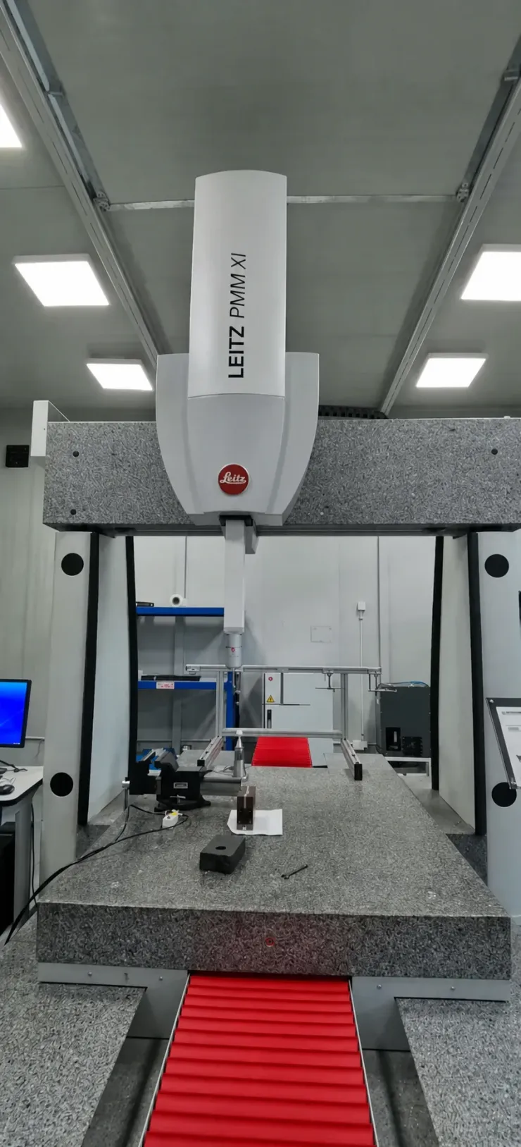
Peel loads come from the part itself. Epoxy prepreg sticks hard enough that debond forces reach 0.5 to 2 MPa at the interface, and trim tabs see the same shear each time a technician cuts a part free. Record surface treatment and the release system as cycle-consumable items, not permanent finishes.
The aerospace parts mold guide covers traceability and tolerance discipline for flight hardware; the composite tool inherits the same evidence burden with a thermal twist.
The CTE Match Rule
Thermal expansion, not budget, is the first tool-material decision. A carbon-epoxy laminate expands roughly 0 to 2 ppm per K along the fiber and 10 to 12 ppm per K through thickness on quasi-isotropic layups. Tool candidates sit at: invar 1.6 ppm per K, carbon-epoxy tooling near 0, tool steel 11 to 12, aluminum 23, laminated epoxy tooling 20 to 50.
The mismatch error is computable before you buy. Take a 1,000 mm tool heated 155 C from ambient: steel grows 1.7 to 1.9 mm, aluminum 3.6 mm, invar 0.25 mm. If the part wants 0.15 mm, the steel tool over-packs the layup by more than 1 mm of arc on a long panel. On curved parts, spring-in after cure commonly lands between 0.25 and 1.5 degrees when the tool was picked for cost instead of the cure window.
Pick against the cure window and the layup, then check the shape. A flat 2 mm skin on a steel tool forgives an aluminum-versus-steel mismatch, because most of the error goes into in-plane length the trim removes. A co-cured channel with bonded stiffeners cannot: 2 ppm per K over 500 mm at a 160 C delta is 0.4 mm of growth, and every bolt hole lands somewhere new.
The Tool Material Ladder
The ladder below orders the candidates by temperature ceiling, cost band and cycle life. Read it against the CTE numbers above: the cheap rungs are also the ones that move most when heated.
| Tool material | CTE ppm per K | Use ceiling | Cost band USD | Cycle life |
|---|---|---|---|---|
| Laminated epoxy tool board | 20 to 50 | 160 to 180 C | 8,000 to 40,000 | 100 to 500 |
| Aluminum 6061 | 23 | about 150 C | 10,000 to 60,000 | 500 to 3,000 |
| P20 or 4140 steel, plated | 11 to 12 | 190 C plus | 30,000 to 150,000 | 5,000 to 20,000 |
| Invar 42 or 4K | 1.6 | 190 C plus | 50,000 to 300,000 | 10,000 plus |
| Carbon-epoxy composite tool | near 0 | 180 to 190 C | 40,000 to 200,000 | 2,000 to 10,000 |
← swipe to scroll →
Table note: bands are typical industry values for aerospace-style prepreg tooling, not quotes. A composite shop may re-coat or rebuild a tool and extend life; confirm CTE certificates for the exact heat lot before releasing a drawing.
Invar is the answer only when slope error is contractual. It costs 2 to 3 times a good steel tool, machines at half the rate, and welds badly, because the heat-affected zone destroys the 1.6 ppm per K property unless rated filler and passes are used.
The steel route is where a die shop earns its place. P20 or 4140 blocks are hard-machined, stress-relieved between operations, then plated. The mold steel heat treatment guide covers the temper and hardness discipline that keeps a machined plate from moving 0.1 mm after the first cure.
Sealing the Tool: Vacuum Architecture
The bag system is where composite tooling differs from metal-forming tooling. A knife-edge groove runs around the perimeter, 3 to 6 mm deep and 2 to 3 mm wide, and the bag sealing tape drops into it to form the vacuum boundary. Keep the groove continuous, with a corner radius no tighter than R5 to R15 mm, because a bag folded into a sharp corner bridges or tears at 0.9 bar differential.
Through-tool vacuum ports carry air out from under the bag. They run 3 to 8 mm in diameter on 100 to 300 mm pitch, each behind a 0.05 to 0.15 mm screen or bleeder so resin cannot plug the path. Drill them at a land or a non-cosmetic zone, never under an A-surface, and leak-test every port to 0.1 to 0.5 mbar-L/s before the tool ships. Above that target the bag collapses unevenly, the ply stack shifts and the part prints porosity.
Two sealing details decide first-pass yield. Vacuum bosses on the tool back land the port tubing above the bag footprint, so a fitting never touches the seal ring. A co-cured insert must register mechanically, with dowel pins and a bolted flange, because 5 to 7 bar of autoclave pressure will walk a loose insert 0.5 to 2 mm across the surface.
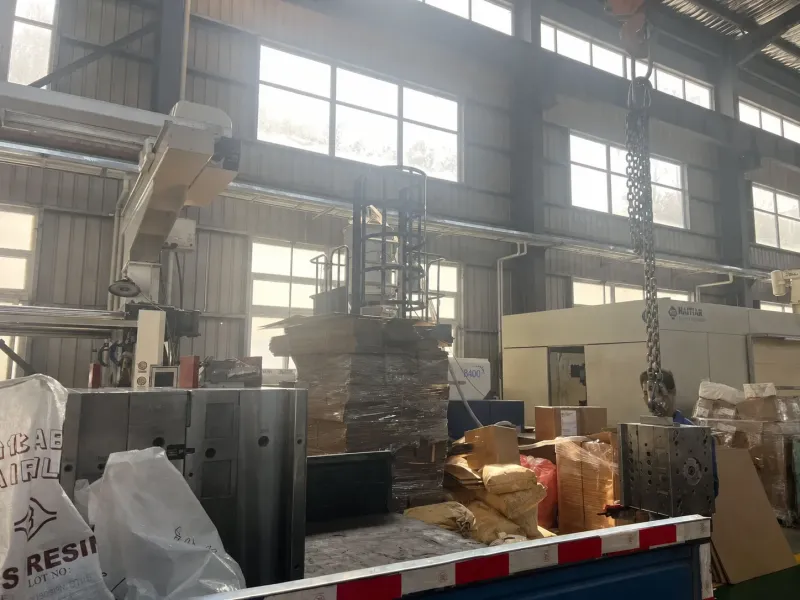
Ply locators and layout guides belong on the drawing with a tolerance: tape guides and locator pads at plus or minus 0.5 mm keep hand layup inside the ply-margin budget. A 2 mm placement error on a 0.125 mm ply edge is a visible line on a Class A face and a resin-starved edge on a structural one.
Surface Finish, Release and Coatings
The part inherits the tool surface exactly. A scratch at Ra 0.2 to 0.4 µm on a polished face prints through fabric in the first part and in every part after it, because epoxy prepreg conforms at 5 to 7 bar while uncured. Polish to the part spec, then cover the tool when idle and log any field repair.
Steel and invar surfaces are nearly always plated. Electroless nickel or nickel-PTFE at 25 to 60 µm seals the pores, cuts outgassing and carries release. Unsealed steel outgasses adsorbed moisture at 180 C, and the vapor bubbles through the laminate as 0.1 to 0.5 mm pits along the fiber weave. A 50 to 200 µm sealant coat closes the remaining micro-porosity and re-applies every 20 to 100 cycles.
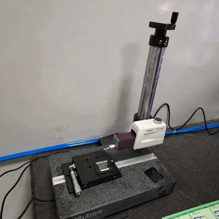
Release systems come in two families: PVA film or paste, a 5 to 25 µm sacrificial barrier dried before layup, and fabric-based releases rebuilt every 5 to 20 pulls. Choose per part count and surface class: a one-off test panel can eat PVA residue, while a bonded fuselage doubler with a 1.5 mm adhesive bond line cannot, because silicone release contaminates bonding zones.
Coating and texture decisions follow the same logic as injection molds: the tool surface is a drawing requirement, not a shop habit. Mirror the finish spec on the print with a measurement method and a repair window, and the shop stops polishing it up at the bench.
Thermal Mass and Tool Temperature Uniformity
A steel tool carries 3 to 6 times the heat capacity of an epoxy-laminate tool of the same shape, which changes the schedule the composite shop can run. The ramp is capped at 1.5 to 5 C per minute by the resin flow and volatiles window, and a heavy tool adds 20 to 60 minutes of soak per side against the autoclave air. On a 12-hour cycle that lag is roughly 6 percent of furnace time.
Uniformity is the acceptance spec. Most cure procedures demand plus or minus 5 C across the tool surface at the part, verified with 12 to 30 thermocouples: 12 on a 600 mm panel, 30 across a 3 m wing tool. Cold spots of 8 to 15 C at ribs and lightening pockets cause local under-cure that a hardness test will find on the wrong side of the part.
That drives tool construction. Production metal tools are cored: honeycomb-backed plates, open-channel interiors with ribs on 100 to 200 mm pitch, or welded tubular stiffeners that double as air or steam passages. A channel wall 15 to 25 mm from the face moves heat laterally fast enough to hold the plus or minus 5 C band.
Massive tools are not automatically worse; they are slower and steadier. They ride through exotherm spikes of 10 to 25 C on thick sections, which is why shops reach for steel or invar on 10 to 30 mm laminate stubs and accept the ramp penalty. Match thermal mass to the thickest part on the tool.
Matching Features and Trip Plates
The form tool only earns its tolerance if the trim tool agrees with it. Parts are trimmed after cure on a router bed or a waterjet table, held in a fixture that references the cured part, not the CAD model. Cured parts drift 0.3 to 1.0 mm cycle to cycle, so a fixture machined straight off the model chases that drift and rejects good parts.
Build the matching set from a captured master. Cure three to five parts, scan them, and machine the trim-fixture locators to the mean of the measured parts, with hold-down posts at plus or minus 0.05 mm against the trim boundaries. Trip plates carry the trim-outline template or the router pick points and should be replaceable and versioned: when the form tool is reworked, the plate is re-shot, not the fixture scrapped.
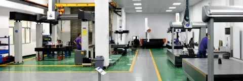
Datum evidence rides on the tool and fixture pair. CMM datum balls or machined datum pads, typically three for a plane plus two for orientation, let the inspection cell re-establish the part coordinate system within 0.05 mm after every cure and prove that the tool surface made a bad angle, not the layup. Read deviations the way an inspection report demands: how to read a CMM report covers the datum and deviation logic that transfers straight to trip-plate approvals.
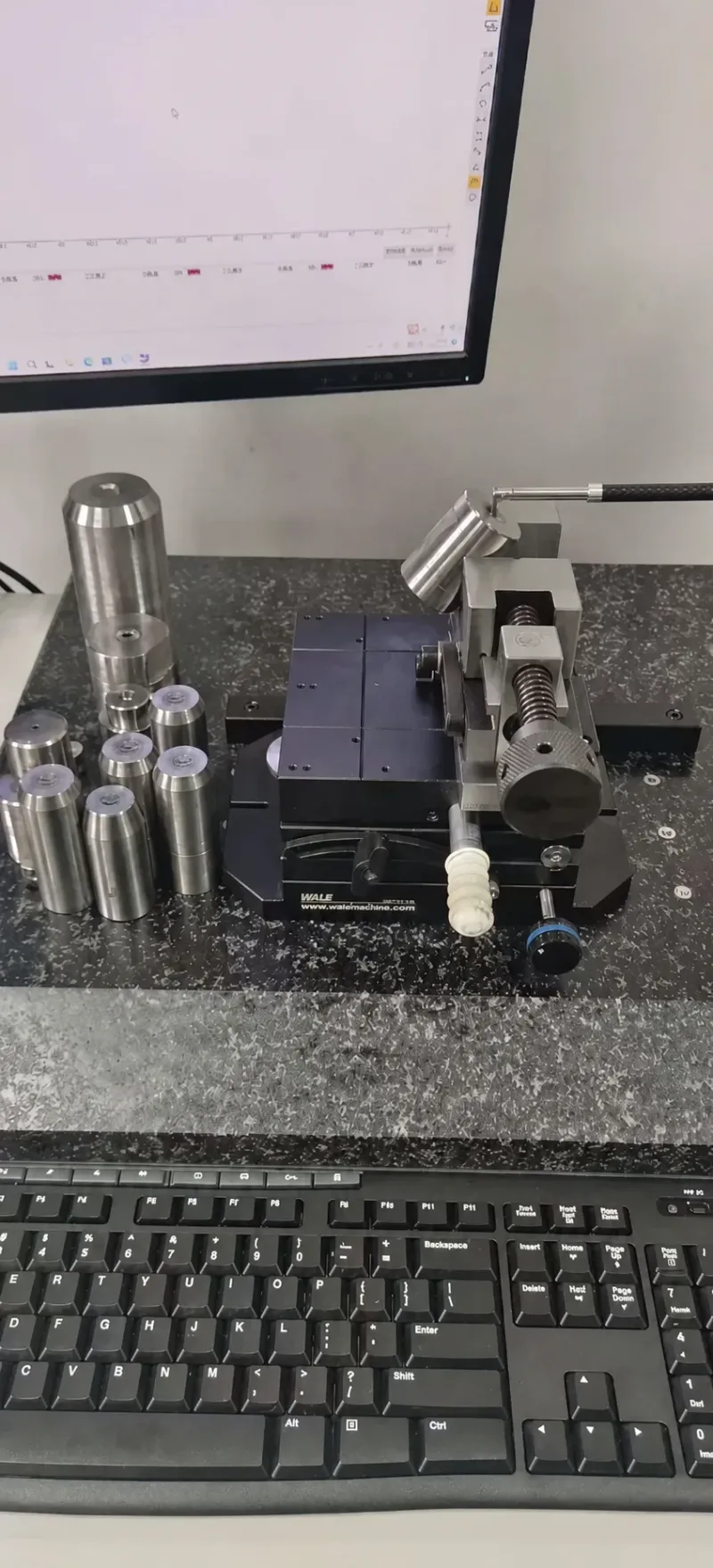
Co-cured metal inserts and machined bushings need the same registration: dowel-located pockets to plus or minus 0.1 mm, with a thermal-growth allowance on the drawing when insert metal and tool CTE differ by more than 5 ppm per K.
Trim and Machining Fixtures
Trim tooling is a die problem in a composite costume. The cured part is held, located and cut, and the fixture takes clamping load, chip blast and constant water. Steel fixtures in 4140 or P20 with hard chrome on the wear pads live 5,000 to 20,000 parts; an aluminum fixture wears its locator bores loose at 0.1 to 0.2 mm within a few hundred clamp cycles.
Specify the holding philosophy before you machine. Vacuum chucking across the A-surface holds thin skins without point loads; hard pad clamps with 1 to 2 kN spread on non-cosmetic lands suit ribs and spars. A clamp that flexes a 2 mm skin 0.5 mm during the cut springs back at release and lands the hole pattern 0.5 mm off.
Router and waterjet boundaries both live on the trip plate. Drill trim boundaries with cut guides every 150 to 250 mm for saw-cut flanges; a waterjet fixture needs a 10 to 20 mm standoff and splash containment. Keep the trim allowance 1.5 to 3 mm outside the final boundary, and machine the fixture to the finished part line, not the raw one.
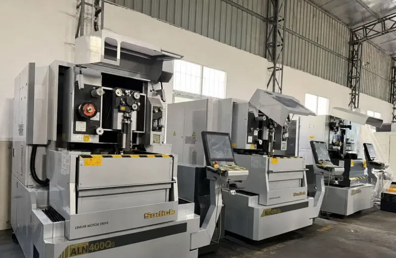
Where the trim fixture shares a shop with stamping or die casting work, the same die-shop competence applies: locate, clamp, cut, gauge. This is exactly the kind of precision metal work DieStrike machines under an IATF 16949 quality system, with plus or minus 0.005 mm on mold work and plus or minus 0.002 mm on the EDM and jig-grinding that makes fixture bores and datum pads repeatable.
Inspection, Acceptance and the Tool File
A composite tool is accepted on four measurable conditions, and all four belong in the tool file before the first layup. Write them as numbers: a shop that accepts a tool on looks spends the difference on scrap parts.
Surface geometry comes first. Scan the working face against CAD with a deviation band of 0.1 to 0.25 mm on Class A surfaces and 0.25 to 0.5 mm on structural lands, reported with the datum scheme the trim fixtures will later use. Measure the face after plating, not after milling, or the report is fiction.
Vacuum integrity comes second. Assemble the bag on the tool, pull 0.8 to 0.95 bar, and hold 10 to 15 minutes under a decay limit set by the shop procedure, commonly under 1 to 2 mbar. Any leak above 0.1 to 0.5 mbar-L/s gets traced to the groove, the port screen or the bag splice, documented, and re-run.
Third is thermal behavior: instrument the full 12 to 30 thermocouple map, run a heat-up and cool-down to cure temperature with no part on the tool, and verify the plus or minus 5 C band plus the ramp time at the thickest section. Fourth is feature truth: knife groove depth and width, port positions, and locator or datum pad coordinates, checked to plus or minus 0.05 mm on datum features.
The tool file then carries the cycle-consumables and the history: release system, sealant coat count, plating type and thickness, rework record, thermocouple map, and the post-cure surface scan. Build the acceptance discipline off a checklist, as in the mold acceptance checklist, and keep the register current so a tool moved between cells carries its evidence with it.
Cost, Life and the Rework Decision
Tool selection is a part-count problem with a temperature ceiling on top. Under 100 cycles at 160 to 180 C, an epoxy laminate tool at 8,000 to 40,000 USD is the rational buy, because it patches and re-seals in an afternoon. From 500 to 3,000 cycles, aluminum 6061 at 10,000 to 60,000 USD machines fast and light. From 5,000 to 20,000 cycles at 190 C, plated P20 or 4140 steel at 30,000 to 150,000 USD is the production answer. Invar at 50,000 to 300,000 USD only when 0.25 degree slope control is written into the contract.
Rework routes differ by material. Epoxy tooling board is forgiving: gouges fill, sand and re-seal within a 0.02 to 0.05 mm repair window. Steel tools are repairable by weld and re-machine, then the whole surface is re-finished because patch plating does not blend. Invar is the worst repair customer in the shop: welding distorts the low-CTE structure, and a bad repair can cost the tool rather than 20 hours of it.
Two decisions deserve writing down before a build. A CTE change after a part is qualified means a new tool, not a rework, because you cannot take expansion out of a steel plate. A design change that moves a rib or a port 50 mm is a re-machine, but moving the knife groove perimeter is a new surface. Leave 2 to 3 mm of plate stock on a machined steel land and 0.02 to 0.05 mm of re-grindable plating, and the tool survives three small revisions instead of dying at the first.
Storage is cheap insurance. Steel and invar tools rust in one humid night, and a 0.05 mm bloom under a sealant coat becomes pits in the next ten parts. Keep tools indoors, coated with a protective film, on soft-edged stands, with the desiccant or VCI record in the tool file.
Common Composite Tool Failures
Most composite tool defects are three causes in a costume: thermal movement, vacuum loss, and surface state. The table maps each symptom to the number that finds it.
| Symptom on the part | Tool-side root cause | Number to check |
|---|---|---|
| Spring-in angle drifts with tool temperature | Tool CTE far from laminate CTE across the cure window | Delta of 2 ppm per K over 1,000 mm at 155 C equals about 0.3 mm |
| Porosity near ribs and lightening pockets | Cold spot slows resin flow, port plugged, bleeder starved | Surface spread under 5 C, ports 3 to 8 mm on 100 to 300 mm pitch |
| Pin marks at the trim boundary | Knife groove bridged or bag torn at a sharp corner | Groove 3 to 6 mm, wrap radius R5 to R15 mm minimum |
| 0.1 to 0.5 mm pits on the A-surface | Unsealed steel outgassing at cure temperature | Plating 25 to 60 µm, sealant 50 to 200 µm, re-coat interval |
| Hole pattern off after trim | Fixture referenced the model, or skin flexed under clamp | Posts to plus or minus 0.05 mm, clamp flex under 0.1 mm |
| Scratch prints through fabric | Polish damage carried into the next cycle | Ra 0.2 to 0.4 µm spec, 0.02 to 0.05 mm repair window |
← swipe to scroll →
Table note: values are typical for carbon-epoxy prepreg autoclave tooling. Confirm the laminate CTE certificate, the cure procedure and the shop leak standard before assigning a defect to the tool.
Four of the six rows are fixed by a number on a drawing rather than a new tool: geometry drift, port plugging, sealant interval and fixture reference are documentation problems that present as scrap. The two rows that need money, the CTE mistake and the destroyed invar surface, are bought at material selection, weeks before the first part.
The Bottom Line
Autoclave composite tooling is designed from four numbers outward: match the tool CTE to the laminate within about 2 ppm per K across the cure window, hold the vacuum architecture at knife grooves 3 to 6 mm and ports 3 to 8 mm on 100 to 300 mm pitch to a 0.1 to 0.5 mbar-L/s leak target, keep the surface at Ra 0.2 to 0.4 µm under a 25 to 60 µm plate and 50 to 200 µm sealant, and prove plus or minus 5 C uniformity with a 12 to 30 thermocouple map. Pick the material ladder by cycle count and temperature ceiling, not by budget alone, and machine the trim and match fixtures to the measured cured part.
DieStrike sits on the metal side of that boundary: we machine composite tool bodies, steel and invar inserts, plating-ready faces, vacuum-port details, and the trim, match and drilling fixtures that hold the cured part. Under an IATF 16949 quality system we work to plus or minus 0.005 mm on mold and fixture work with plus or minus 0.002 mm on EDM and jig grinding, HRC 62 maximum heat treatment, on 120+ machines. The autoclave stays in your shop; the dimensional truth of the tool comes off our grinder.
Standard components ship in 3 to 7 days and tool lead times run 2 to 5 weeks, with tier-1 references including TE, Amphenol, Luxshare and Dongshan. Send the laminate layup schedule, the cure temperature, the slope tolerance and the part count, and we will quote the tool material against the CTE and cycle-life math rather than the catalog. Route the print through contact and die and fixture manufacturing.
KEEP READING
Related Reading
How to Design Molds for Aerospace Parts
Tolerance, material and traceability decisions for flight hardware molds under AS9100 programs.
Read articleArticleHow to Specify Mold Steel Heat Treatment
Austenitize, temper and hardness windows that decide whether a tool steel face survives a cure cycle.
Read articleArticleHow to Read a CMM Report
How to pull datum, deviation and capability evidence out of a coordinate measuring machine report.
Read articleServiceDie and Fixture Manufacturing
IATF 16949 machining of metal tool bodies, inserts and trim fixtures to plus or minus 0.005 mm.
Read articleNEXT STEP
Ready to Start Your Mold?
Send us your element dimensions or part numbers — our team responds within 24 hours. Pricing and lead time come with the answer.

Written by
Ray ChanExport Brand Manager at DieStrike. Ray helps global importers, distributors and OEMs source factory-direct molds and mold parts.