
Hard Chrome Plating for Mold Components: Wear, Limits and Bake
Table of Contents
A progressive die with 40 µm of hard chrome on every piercing punch shipped back from a subcontract plater with no bake instruction on the purchase order. Fourteen through-hardened D2 punches, at HRC 60-62, fractured under the plate within nine working days of a 1,400 stroke-per-minute run. The line lost six days, the rebuild took three weeks, and the fracture surfaces pointed straight at absorbed hydrogen. Hard chrome on mold and die components is a dimensional and metallurgical contract, not a dip in a tank, and this guide is the decision card for that contract.
The numbers below cover electrodeposited chromium thickness rules, throwing power limits, post-plate bake physics, hexavalent regulation against trivalent chemistry, and a line-by-line comparison with electroless nickel, PVD and nitriding, written for buyers who send tooling out to a plating house.
The Snapshot
- Hard chrome plate runs 65-70 HRC (850-1,000 HV) with the lowest dry friction of the plating family, 0.3-0.4 against 0.6 for bare tool steel. Mold wear films go on at 25-100 µm; worn-shaft rebuilds reach 500 µm and then must be ground back.
- Throwing power is the structural weakness: a bore deeper than roughly 1.5 times its diameter stays bare without an auxiliary anode, thickness varies 20-40 percent across a contour, and edges build 2-3 times nominal without robbers.
- The plate grows outward at the full thickness per surface, so every critical dimension is machined undersize before plating and ground or lapped to size after. On ±0.005 mm mold work the pre-plate allowance is a drawing dimension, not a plater's guess.
- Plating drives 5-40 ppm of hydrogen into the steel. A 130-200°C bake for 4-24 hours, started within four hours of plating, is non-negotiable above 50 HRC, and the bake schedule belongs on the drawing that cuts the component.
What Hard Chrome Plating Delivers on Mold Components
Hard chrome is chromium electrodeposited from a chromic-acid bath under controlled current, covered for engineering use by ASTM B650. Unlike decorative chrome measured in fractions of a micron, engineering builds run from 1 µm to more than 500 µm. On mold and die hardware the working range is 25-100 µm as a wear film, with 200-500 µm reserved for rebuilding worn surfaces that will be reground afterward.
Hardness is the headline number: 65-70 HRC, or 850-1,000 HV as-plated, which sits above most through-hardened tool steels at HRC 58-62 and far above pre-hardened cavity steels. The friction coefficient against steel under dry sliding is 0.3-0.4, the lowest in the plating family against electroless nickel at roughly 0.4-0.45. That combination, high hardness plus low friction, is what makes chrome the default on steel-on-steel sliding contacts where galling, not abrasion, is the failure mode.
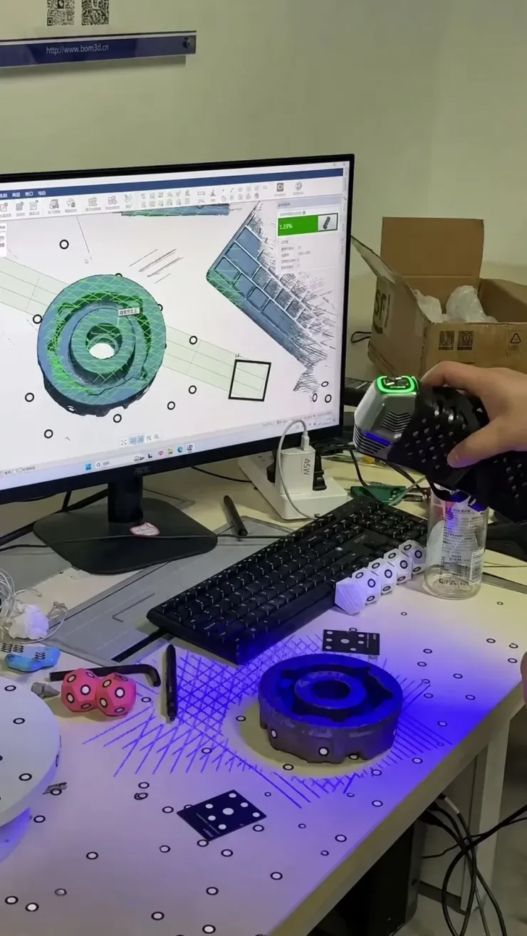
The components that carry it are the sliding ones: mold slides and wear plates, ejector punches and stripper bolts, lifters, pin cores, side-core blades, and on the press side the punch faces and guide posts of high-volume stamping tools. A 50 µm plate on an SKD11 slide running against a hardened track typically stretches galling-free life from tens of thousands of cycles to several hundred thousand, and repair-versus-replace decisions usually favor plating because the film, not the steel, is the sacrificial layer.
Rebuild is chrome's second trade. A core, shaft or boss worn 0.3-0.5 mm undersize takes a 300-500 µm build, then goes back on a jig grinder for the final cut. That route is how a worn insert returns to a ±0.005 mm finished dimension instead of becoming scrap, and it belongs in the same conversation as the mold repair and maintenance plan rather than in a new-tool quote.
Corrosion needs a caveat. Dense chrome is chemically resistant to the acids that PVC and some flame-retardant resins release, and it shields the steel beneath it. But hard plate is microcracked, and the cracks are corrosion paths. A 25 µm build commonly passes under 100 hours of ASTM B117 salt spray before red rust at the crack lines, so a barrier-driven spec needs 50-100 µm, a low-stress crack-free bath, or a sealed plate. If corrosion without any cracks is the actual requirement, that is electroless nickel work, not chrome.
Two limits close the capability list. The film is thin relative to its hardness demand, so it needs a supported substrate: plating onto steel below roughly HRC 45 produces a hard shell over a soft anvil that dents and spalls under load. Through-hardened tooling to HRC 62, which is the ceiling we cut at, is the right partner. And service temperature tops out near 300-400°C, where chrome oxidizes to brittle oxide; aluminum die-casting faces at 600°C melt-contact are nitriding or PVD territory, not chrome.
Throwing Power: Where the Plate Never Lands
Chrome follows current, and current follows geometry. Deposit thickness at any point is set by local current density, which is decided by anode layout and part shape, not by dwell time alone. This is why chrome throwing power, the ability to plate recessed areas, is the worst in the plating family, and why the coverage map of a mold component has blind spots that surprise first-time buyers.
Internal bores are the classic failure. Current crowds at the bore mouth and starves in the depth. A Ø10 mm hole that runs 15 mm deep plates thin at the entrance and reaches bare steel a few millimeters in; anything deeper than roughly 1.5 times the diameter needs an auxiliary anode pushed inside the bore. No workable cathode filler exists for blind geometry, so the honest options are internal anodes or a different process. Bores that never saw an anode come back reading 0 µm at the floor, and a bore that stays bare is a bore that keeps corroding.
Across an open contour, thickness varies 20-40 percent between flat faces and the points nearest the anode. External corners and edge breaks concentrate current and build 2-3 times nominal, which is where the plate turns dark, nodular and eventually flakes. Robber anodes placed near recesses and thieves (conductive shields) placed near edges are the standard corrections, and both are quoted line items. A chrome job priced without anode tooling for a shaped mold insert is an incomplete quote.
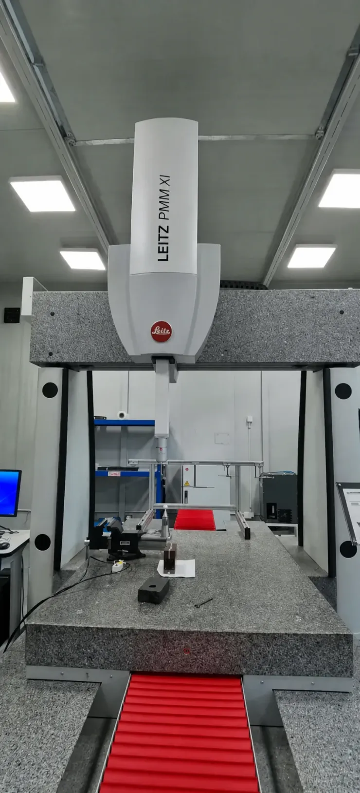
What chrome cannot reach at all: enclosed cooling channels, blind holes below the anode-access limit, faces masked for fit, and assembled sub-plates where solution circulation is dead. A plated slide shows 50 µm on the wear face and 0 µm inside the water circuit. Electroless nickel deposits chemically on every wetted surface with a ±10 percent spread, and the coverage argument in our electroless nickel guide is exactly the geometry chrome loses on. The right 2026 spec is often a hybrid: chrome on the sliding face, EN or nothing inside.
Finally, coverage is a drawing statement. Specify plated areas, masked areas and bore depths with a marked-up print, not a blanket "chrome 50 µm" note. Masking errors and starving recesses are the two most common reasons a chrome batch comes back non-conforming, and both are preventable before the part ships to the plater.
Pre-Plate Undersize and Post-Plate Grind
Electroplated chromium deposits on the outside of the part, adding its full thickness to every unmasked surface. A Ø20.000 mm pin plated at 50 µm comes back at Ø20.100 mm. A shut-off face plated at 25 µm closes the mating gap by 25 µm. Two plated shut-off faces close it by 50 µm. On a tool held to ±0.005 mm, a forgotten 50 µm build is one tenth of tolerance per surface, and the arithmetic has to be done before the first cut, not after the tank.
Working rule: machine every plated dimension undersize by the target thickness, then finish after plating by grind, lap or honed to the drawing nominal. For a slide wear face at 50 µm, grind the pre-plate size 0.05 mm low and let the plate bring it back. For a pin at 25 µm, turn it 0.05 mm under nominal diameter, plate, then jig-grind the Ø back to size within ±0.002 mm. DieStrike puts the pre-plate dimension and the finished dimension on the same drawing so the plater machines to one number and the grinder inspects to the other.
Plated-before-grind versus plated-and-used-as-plate has different cost lines. As-plated 25 µm on a non-fit slide face is acceptable with a ±30 percent thickness band, and the part skips the second grinding pass. Fit surfaces, seal bores and shut-offs require the grind-back, which is why chrome adds two process steps that electroless nickel's ±10 percent uniformity often avoids. The buyer-side test is simple: any dimension carrying a plate allowance without a stated post-plate operation is a dimension someone guessed.
Edge radii are part of the same contract. A sharp 90° corner concentrates current and builds 2-3 times the nominal thickness, and thick plate at a corner is stressed plate ready to flake. Radiused edges of at least 0.2 mm, and 0.5 mm where the geometry allows, keep the corner build within one thickness of the flat. Chamfered or radiused pre-plate edges are a machining instruction, cheap to give and expensive to retrofit after heat treatment.
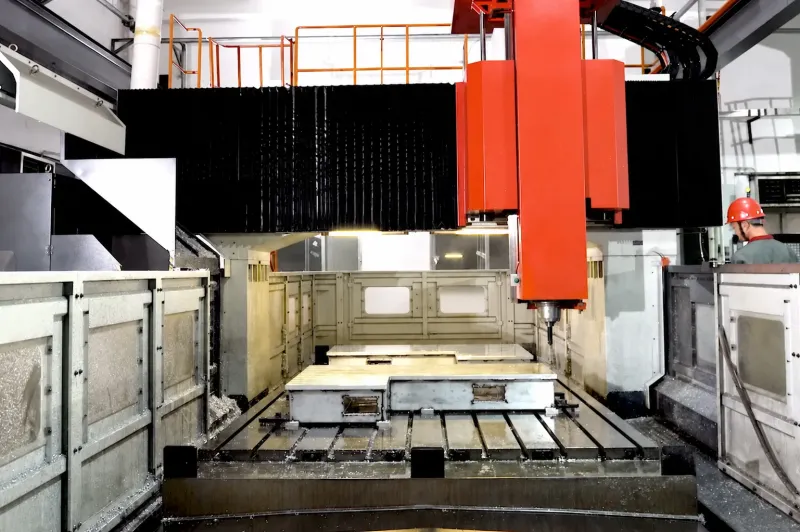
Rebuild builds break the same rule in the other direction. A worn shaft at 0.4 mm undersize takes 400-500 µm of chrome, then needs 0.35-0.45 mm of grinding to return to nominal. Deposits above roughly 100-150 µm in one continuous cycle carry accumulating internal stress, so a competent plater splits heavy builds into two or three strikes with intermediate hydrogen bakes, not one eight-hour dump. Heavy plate on a part nobody intends to regrind is a thickness with no dimensional owner.
Internal Stress, Microcracks and Absorbed Hydrogen
Hard chrome as-plated sits in tension at 200-500 MPa, the highest intrinsic stress of any common engineering deposit. The plate relieves part of that stress by cracking: a standard Cr(VI) bath produces a microcrack network, and the crack density distinguishes the families. Decorative chromium cracks at 500-1,000 cracks per millimeter; hard chromium from a normal sulfate bath is self-cracking but finer, and modified low-stress or crack-free baths suppress the network deliberately.
Microcracks are not a defect for wear use. They hold lubricant, relieve stress progressively and prevent one large spall. They are a defect for corrosion use: each crack is an electrolyte highway to the steel below, which is why thin chrome fails salt spray early while a crack-free electroless nickel deposit acts as a barrier film instead.
The dangerous by-product is hydrogen. Every aqueous plate co-deposits atomic hydrogen, and cathodic current drives it into the steel lattice. A plated tool component commonly holds 5-40 ppm of absorbed hydrogen, concentrated in the highest-hardness, highest-stress regions: under the plate, at crack roots, at the radius of a loaded corner. Below 50 HRC and 1,000 MPa tensile strength most of that hydrogen diffuses out harmlessly within days. Above that threshold, high-strength martensitic tool steel is susceptible to hydrogen-assisted delayed fracture: a part plates clean, grinds clean, runs for days or weeks, then cracks without warning at a stress far below its static capacity.
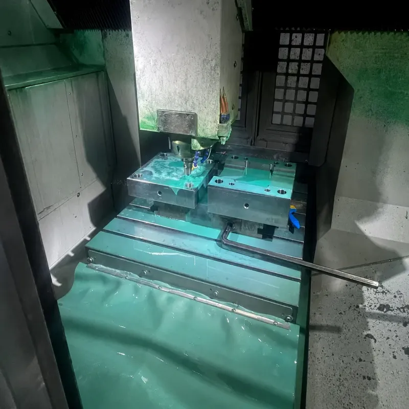
Through-hardened punch steels are the exposed population. D2 and DPM-FX at HRC 60-62, M2 high-speed at HRC 64-66, SKD11 at HRC 58-62 and carburized case-hardened steels sit squarely in the susceptibility band, and they are exactly the components buyers habitually chrome for wear. Steel above roughly 1,000 MPa ultimate tensile strength is the standard trigger for mandatory relief heat treatment, and every tool steel above HRC 50 clears that bar. The failure sequence of the punch story at the top of this guide is the textbook signature: plate, no bake, four days of running, cracks under the plate at the stress concentrators.
The Mandatory Post-Plate Bake
The control is low-heat baking shortly after plating, and the physics is diffusion. At 130-200°C, absorbed hydrogen becomes mobile enough to leave the steel before it gathers at traps; waiting past a few hours loses part of the charge into irreversible embrittlement. The workhorse schedule for tooling: 190-200°C for 4 hours minimum, measured from when the part core reaches temperature. Hydrogen-embrittlement relief guidance in standards such as ASTM F1470, and automotive plating specs built on it, converge on this band for high-strength steel.
Where hardness or temper margin pushes you lower, time extends: a 130-150°C bake needs 12-24 hours to do comparable work, and it is the schedule for steels tempered near their plating limit. Two clocks matter. The bake should start within 4 hours of plating exit; a part that sits overnight at room temperature has already begun re-trapping hydrogen. And the 4-hour soak at 195°C is a floor on heavy builds: a 300 µm rebuild on a large shaft needs the longer side of the window because hydrogen has more path to diffuse out.
Does the bake soften the tool? For the mold-maker's question set: below roughly 500°C no common tool steel loses measurable hardness, so D2 at HRC 60 and H13 at HRC 50 both shrug off a 200°C, 4-hour bake. The exceptions are diffusion treatments, not base steels. A nitrided layer can drop 1-2 HRC at nitriding-adjacent temperatures, so on a plasma-nitrided component the honest sequences are plate-then-nitride-impossible (chrome melts into the case), bake-cold, or skip the chrome. If a component needs both, choose one surface treatment. Our breakdown of nitriding versus PVD covers that decision.
Buyer-side enforcement: the bake schedule is a line on the purchase order, with temperature, hold time, and the four-hour start window stated, and the plater's oven log is one of the batch records returned with the parts. Under an IATF 16949 system this traceability is not paperwork for its own sake; it is the only mechanism that proves a fractured punch was not relieved before it was sent to a failure analysis.
Hexavalent Chrome: The Regulatory Drag
Conventional hard chrome is plated from chromic acid, Cr(VI), a carcinogen by classification and the most regulated plating chemistry in the shop. The operating consequences are commercial, not just environmental, and they belong in a 2026 sourcing decision.
Under EU REACH, Cr(VI) for plating is an authorisation-listed substance (Annex XIV): installations keep running only under granted or applied-for authorisations with time-limited review, and the same constraint propagates to the supplier chain, because an unauthorized facility cannot lawfully serve EU production. In the US, the EPA's hard and decorative plating NESHAP under the Clean Air Act caps chromic-acid mist emissions from each tank, forcing add-on fume treatment, housekeeping and monitoring records; wastewater leaves under NPDES metal limits that many cities tighten further. On top, worker exposure sits under OSHA's 25 µg/m³ action level for hexavalent chromium with 8-hour PELs of 5 µg/m³.
Three commercial effects follow. Platers carrying authorisations, mist suppression and chromium-bearing sludge contracts price that overhead into every batch, and the spread versus a decade ago is visible in quotes. Supply is thinning: shops convert lines, close tanks or drop small plating customers as compliance cost outruns tank revenue, so a mold program's "any chrome shop" assumption has a rising failure chance at the second-source stage. And parts can carry the regulation home: automotive customers under IMDS and ELV reporting increasingly ask about chromium process residues, and a component family with an undocumented plating source becomes a program risk on documentation alone.
None of this says hard chrome is dead. It says the Cr(VI) route now needs a named, permitted, documented plater with spare capacity, and that conversion options deserve a quote at the RFQ stage rather than after the tank line disappears.
Trivalent Chrome: What It Fixes and What It Costs
Trivalent chromium (Cr(III)) baths, sold under names like HTe and Black-Chrome-type processes, plate from chromium sulfate or chromium chloride chemistry instead of chromic acid. The mist is far less toxic, no authorisation is required in the same form, emission and sludge burdens shrink, and the bath tolerates wider temperature swings. Hydrogen-embrittlement behavior changes too: Cr(III) deposits plate with substantially less occluded hydrogen and lower tensile stress, so relief bakes remain good practice but the fracture cliff softens below the Cr(VI) danger zone.
The property sheet pays for the permit. Trivalent hard chrome reaches 60-68 HRC (roughly 800-900 HV) against 65-70 HRC for Cr(VI), and its ductility and wear behavior are narrower: as-thickened cracking arrives earlier, and heavy builds above 100-150 µm are outside most trivalent baths, which were engineered near the thin, uniform, decorative-plus-light-wear envelope. Bath control is fussier (organic additives, stricter temperature and metal concentration windows), first-year cost on small components runs 20-50 percent above conventional chrome, and throwing power improves modestly but does not approach electroless nickel.
The sourcing read for mold components: trivalent is the conversion path for the thin, dimensionally forgiving population, pin cores and small slides at 10-50 µm where 62-66 HRC covers the duty and the bake debate shrinks. Heavy 300-500 µm rebuilds and maximum-wear 70 HRC films still live in the hexavalent world, which is exactly where the permit and plater-availability risk concentrates. Ask every plater for both routes at RFQ; ask which tank your geometry lands in.
Bath Process Window and Plating Defects
The bath decides what the plate is, not just how thick it runs. A standard sulfate hard-chrome bath carries 220-250 g/L chromic acid with the sulfate catalyst at roughly 1 percent of the CrO3, about 2.2-2.5 g/L, and trivalent chromium held at 0.5-2.0 g/L by anode-area balance. Cathode efficiency sits at only 10-25 percent; most of the current evolves hydrogen gas at the part. That single fact explains the embrittlement physics of the last two sections.
Temperature and current density are paired, and the pair sets hardness, stress and crack character. The engineering window runs 50-60°C at 15-30 A/dm². Inside it, colder and hotter matters: at 50-55°C and 25-30 A/dm² you get the 65-70 HRC, high-stress, microcracked plate mold work needs. At 60°C and 15 A/dm² the same bath yields soft, low-stress, crack-free plate closer to decorative behavior. Deposition runs 12-25 µm per hour, so a 25 µm wear film takes 1.5-2 hours and a 100 µm build takes 4-8 hours of tank time plus strike, preheat and bake.
Preparation rules outlive the chemistry. The surface entering the tank should read Ra 3 µm or better; plate replicates roughness and traps cleaning fluid in the valleys. Wire-EDM recast and its sulfide stain must be ground or polished away, typically 0.02-0.05 mm, before any chrome goes on hardened steel. Parts preheat in the bath 5-15 minutes with no current to prevent flash rust, then strike at a higher current density for one to two minutes for adhesion.
The defect list maps directly to that window. Hydrogen burns, the dark nodular porous growth at corners, come from current density too high for the geometry or from starved agitation. Blistering and peeling trace to contaminated prep or a skipped strike. Pitting arrives with dirty baths and high current. Flaking at edges combines 2-3x corner build with as-plated tensile stress at 200-500 MPa. Every one of these is preventable with thieves, robbers, filtration and an honest current profile agreed before the batch.
Verification belongs on the purchase order. Thickness on steel is measured magnetically to ASTM B499 practice, on a coupon from the same rack and on the part's flats. A competent batch file carries the rectifier amp-hours, the bath temperature log, the bake oven chart, and the pre- and post-grind dimensional readings. If a plater cannot produce four of those records, the chrome is not a process, it is a color.
Hard Chrome vs Electroless Nickel, PVD and Nitriding
Four surface treatments compete on mold and die components, and each wins where its physics fits. The table is the decision card; the rows that matter most are thickness, reach, hardness, bake burden and regulatory drag.
| Property | Hard chrome | Electroless nickel | PVD (TiN, CrN, DLC) | Nitriding |
|---|---|---|---|---|
| Hardness | 850-1,000 HV, 65-70 HRC | 500-700 HV as-plated | 2,000-3,000 HV | 950-1,200 HV compound layer |
| Typical thickness | 25-100 µm, rebuilds to 500 µm | 5-50 µm | 2-4 µm | 0.1-0.6 mm diffused case |
| Dry friction | 0.30-0.40, lowest of plating family | 0.35-0.45 | TiN 0.4, DLC 0.05-0.15 | 0.4-0.6, galling-resistant |
| Coverage on complex shape | Poor throwing power, 20-40 percent variation | Uniform within ±10 percent | Line-of-sight only | Gas reaches all exposed faces |
| Internal bores | Bare without an auxiliary anode | Fully coated | Not coatable | Case forms in open bores |
| Dimensional step | Pre-plate undersize, post-plate grind | Machine to 2x allowance, often no grind | Negligible at 2-4 µm | Growth 10-20 percent of case depth |
| Hydrogen embrittlement | High, bake mandatory above 50 HRC | Lower, relief bake still standard | Negligible, vacuum process | None |
| Corrosion at 25 µm | Under 100 h B117, microcracked | High-P passes 500-1,000 h B117 | Dense but pinhole-dependent | Poor, weak barrier |
| Strip and re-plate | Anodic strip hard, re-etch needed | Chemical strip clean | Difficult, often scrap | Only by grinding case away |
| Regulatory load | Cr(VI) permits, REACH, NESHAP | Nickel sensitizer controls | Low | Low, ammonia for gas baths |
| Cost signal | Low per part, heavy prep and grind labor | Medium per batch | $150-600 per tool set | Medium per batch, no post-grind |
| Best fit | Sliding wear, rebuild, thick films | Corrosion, internal surfaces, release | Glass-filled abrasion, sticky resins | Load-bearing dies, hot service |
← swipe to scroll →
Table note: values are typical published industry figures for production treatments on tool steel. Real results depend on substrate, bath chemistry, pretreatment and geometry, so every call-out should carry a coupon requirement and a batch certificate.
Read the table as a physics story. Chrome buys thickness at a low hardness premium: 100 µm of 900 HV is wear stock you can grind through and re-plate, which neither a 3 µm PVD film nor a diffused nitride case can imitate. EN buys uniformity and corrosion, not hardness. PVD buys the hardest surface and the least dimensional disturbance, in a chamber with line-of-sight limits. Nitriding buys a load-bearing case into the steel itself.
Combinations beat single picks on high-volume tooling. A chrome-plated slide with a DLC-topped shut-off, a nitrided die block with chrome-rebuilt pilots, or an EN-lined water circuit with chrome on the exterior wear faces each pair one treatment's strength with another's. Sequence rules govern: plate before PVD never works over thick builds, nitriding before chrome loses 1-2 HRC in the bake question, and any stack needs the grind step preserved between layers.
When to Choose Hard Chrome, and When Not To
Choose hard chrome when four conditions hold at once. The dominant wear mode is sliding steel-on-steel contact, galling or adhesion, not glass-abrasion. The needed film is 25 µm or thicker, or the job is a 200-500 µm rebuild. The component is grindable after plating to hold ±0.005 mm finished tolerance. And the steel, typically D2, M2, SKD11 or H13 above HRC 50, can receive a documented 190-200°C hydrogen bake within four hours of the tank.
Skip chrome when the geometry, the steel or the film you actually need belongs elsewhere. Closed bores without anode access plate bare; that is electroless nickel work. Glass-filled resin abrasion wants 2,000-3,000 HV vapor films, where a 25 µm chrome wear allowance mostly buys nothing over a 3 µm TiN on the same gate land. Cosmetic polished faces you cannot re-grind after plating cannot absorb 20-40 percent thickness variation. Nitrided components should not be chrome-plated and baked. Ultra-high-strength small pins above roughly 1,300 MPa carry real delayed-fracture risk even after a perfect bake, and solid carbide or a different surface is the braver engineering answer. Aluminum die-casting contact faces above 400°C oxidize chrome and solder alloy to it.
The RFQ fields that make or break the batch are these:
- Standard and class. Hard chrome to ASTM B650, engineering plate, with a minimum hardness call of 850 HV.
- Thickness with both dimensions. Finished thickness per surface plus the pre-plate dimension for every fit, for example 50 µm on a Ø19.900 mm pre-grind pin.
- Marked-up coverage map. Plated areas, masked areas and bore depths on a drawing, never a blanket note.
- Edge preparation. All coated edges radiused 0.5 mm before plating, EDM recast fully removed.
- Bake schedule. 190-200°C for 4 hours minimum, started within 4 hours of plating, oven chart returned with the batch.
- Verification. Magnetic coupon thickness to ASTM B499, post-plate grind to drawing, CMM report on fit surfaces.
- Named plater. One facility with current REACH or NESHAP status identified on the paper, for audit and second-source continuity.
At DieStrike the plating tank stays an outside service, but the two numbers that decide the outcome, the bake schedule and the pre-plate dimensions, are specified on the drawings we cut. Standard components ship in 3-7 days, so a chrome call-out is priced into the routing with the grind pass reserved after the tank, before final CMM. Our ejector pin and slide families are the parts that carry these notes most often.
FAQ
Q1. How thick should hard chrome be on a mold slide?
25-50 µm covers sliding wear on hardened slides, lifters and punch faces; 50-100 µm serves heavier duty or light repair. Anything above 150 µm is rebuild territory and must be ground back to size after plating. Specifying over 100 µm on a finish dimension without a grind pass is the most common drawing error we see.
Q2. Do I really have to bake every chrome-plated tool component?
Every component above roughly 50 HRC or 1,000 MPa tensile, yes, at 130-200°C for 4-24 hours started within 4 hours of plating. Pre-hardened P20 at HRC 30-34 is the usual exemption. The argument to bake anyway is cost: four hours in an oven against the six-day line stop and three-week rebuild from the fractured punch set this article opens with.
Q3. Will trivalent chrome replace hexavalent for mold parts?
For films at or under 50-75 µm on small and medium components, often yes: trivalent reaches 60-68 HRC with less hydrogen uptake and lighter permits, at a 20-50 percent price premium. Heavy rebuilds and maximum-wear 65-70 HRC films still need conventional Cr(VI) chemistry today, from a permitted and documented plater.
Q4. Can chrome plate the inside of a cooling bore?
Not reliably. Beyond about 1.5 bore depths the plate starves, and the bore floor reads 0 µm without an auxiliary anode. Even with internal anodes, circulation and gas entrapment make long small-diameter bores a coin flip. Electroless nickel is the correct answer when internal surfaces must be covered.
Q5. How many times can a component be stripped and re-chromed?
Practically two to three cycles. Anodic strip of chrome attacks the steel and re-introduces hydrogen, and each regrind after plating removes base material. The economics flip to a new component once the rebuild leaves less than 0.05 mm of grind stock on the critical section, which is why the repair decision should happen against a dimensioned wear record, not a memory.
The Bottom Line
Hard chrome earns its place on mold and die components when sliding wear needs 25-100 µm of 65-70 HRC film with friction at 0.3-0.4, when a worn shaft needs a 300-500 µm rebuild, and when the buyer controls the three variables that decide the outcome: pre-plate dimensions on the drawing, a 130-200°C bake within four hours on every part above 50 HRC, and a named, permitted plater for the Cr(VI) route. It loses to electroless nickel inside bores, to PVD against glass-filled abrasion, and to nitriding under hot load-bearing duty. Trivalent chemistry already owns the thin-film half of the workload at a 20-50 percent premium, and the conversion line is drawn where heavy builds meet heavy permits. DieStrike tools mold and die components to ±0.005 mm, ±0.002 mm on EDM and jig grinding, under an IATF 16949 system, with bake schedules and pre-plate sizes stated before the steel is cut. Send the drawings, the resin and the shot-volume plan through the contact form and we will return a surface-treatment routing note within 24 hours.
KEEP READING
Related Reading
Electroless Nickel Plating for Mold Surfaces: When It Beats PVD
Autocatalytic Ni-P at 5-50 µm, uniform on every surface, and the reach inside bores that chrome loses.
Read articleArticleNitriding vs PVD Coatings for Mold Steel: Which Surface Treatment When
Diffusion cases at 0.1-0.5 mm against 2-4 µm vacuum films on hardness, toughness and repair route.
Read articleArticleDLC Coating for Mold Components: When It Pays Off
Diamond-like carbon at 2,000-3,000 HV and friction 0.05-0.15 for the release cases chrome cannot match.
Read articleServiceMold Repair and Maintenance
Strip, rebuild and regrind support for worn chrome-plated components from an IATF 16949 mold maker.
Read articleNEXT STEP
Ready to Start Your Mold?
Send us your element dimensions or part numbers — our team responds within 24 hours. Pricing and lead time come with the answer.

Written by
Ray ChanExport Brand Manager at DieStrike. Ray helps global importers, distributors and OEMs source factory-direct molds and mold parts.